Varitronics Inc.
Leading the way with innovative Doctor ~ Nurse Call System technology.
Call us at 1-800-345-1244.Varitronics' Contact Information

Home About Us Affiliations Contact Us FAQ Photo Gallery Product Menu Request Info Technical Specs

CS2000 Technical Specification SPACE Photo Gallery SPACE Varitronics Product Specification

CS2000 Installation Instructions For Common Line Receptacle Units
New Construction Only

UNPACKING
Each CS2000 unit is individually wrapped in a box. Using a knife, carefully slit the box open, making sure that the blade of the knife extends no further than is necessary. Inside the box is the CS2000 unit wrapped in bubble pack. Remove the bubble pack.

IDENTIFYING EACH UNIT
Each CS2000 unit is factory set for specific room. Each unit has a dot over the row corresponding to the room number. The master, unit, which is always placed in Room #1 and is marked #1, is the unit from which all programming functions are accomplished.

REQUIREMENTS
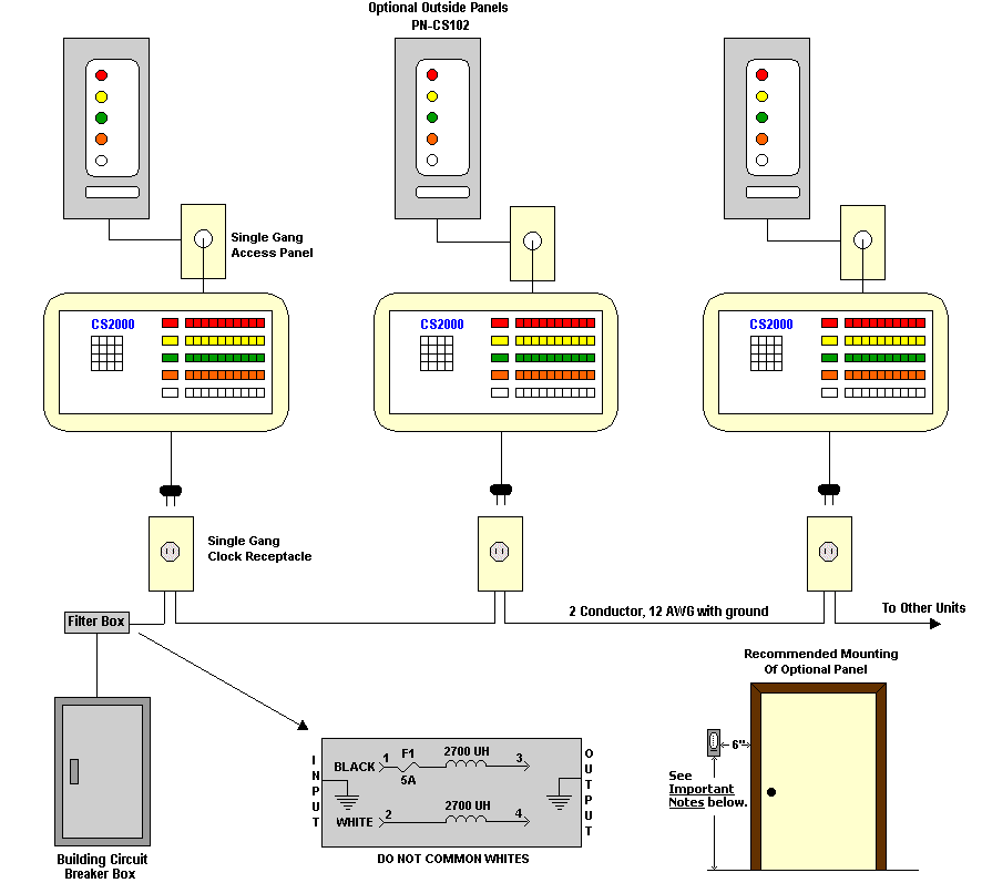
A single dedicated common line receptacle is used for new construction installations. All the units are plugged into the same line. There is no limit on the amount of units that can plug into this line. A filter box is provided that is connected in series with the common dedicated line to the circuit breaker box. It is important to understand that both the HOT (black) and NEUTRAL (white) be connected in series with the line. Do not common the whites.

OPTIONAL MONITOR OR SWITCH PANELS
If optional outside monitor or SWITCH panels are used, please see separate technical specification,
CS2000 Installation Of Optional Outside Panel Or Switch Panel.

BACK BOX NOTES
Back boxes and cables for optional panels are provided by Varitronics. See diagram below for recommended mounting distances. Single gang back boxes are provided by others. These boxes are usually placed behind the CS2000 unit. For exact placement of single gang boxes please contact the architect or administrator.

Dedicated Common Line Receptacle For New Construction

CS2000: New Construction Diagram

Important Notes:
  1. Connect filter box in series with 115V line.
  2. Mount filter near circuit breaker box.
  3. Mount filter in an easily accessible location,
    but do not mount in ceiling.
  4. Filter provided by Varitronics.
  5. Current draw per unit: 20 mA for 10 station units,
    40 mA for 20 station units.
  6. Back boxes and cable for optional panels are
    provided by Varitronics Inc.
  7. For ergonomic height, we recommend mounting the outside room back box 58 inches from the bottom of the floor. However, this does not meet ADA regulations. See Cautions.
  8. Use clock receptacles.
  9. If you have any question, call technical support
    at 610-356-3995.
Cautions:
  1. Do not common whites (Neutral).
  2. Be sure that all receptacles are grounded.
  3. Please refer to national ADA regulations for
    proper back box mounting height of all room panels